The application
High-speed interconnections need to be evaluated through the physical interfaces that carry the signal. For an assembled PCB or backplane, that includes the board, connector, probe, and measurement path.
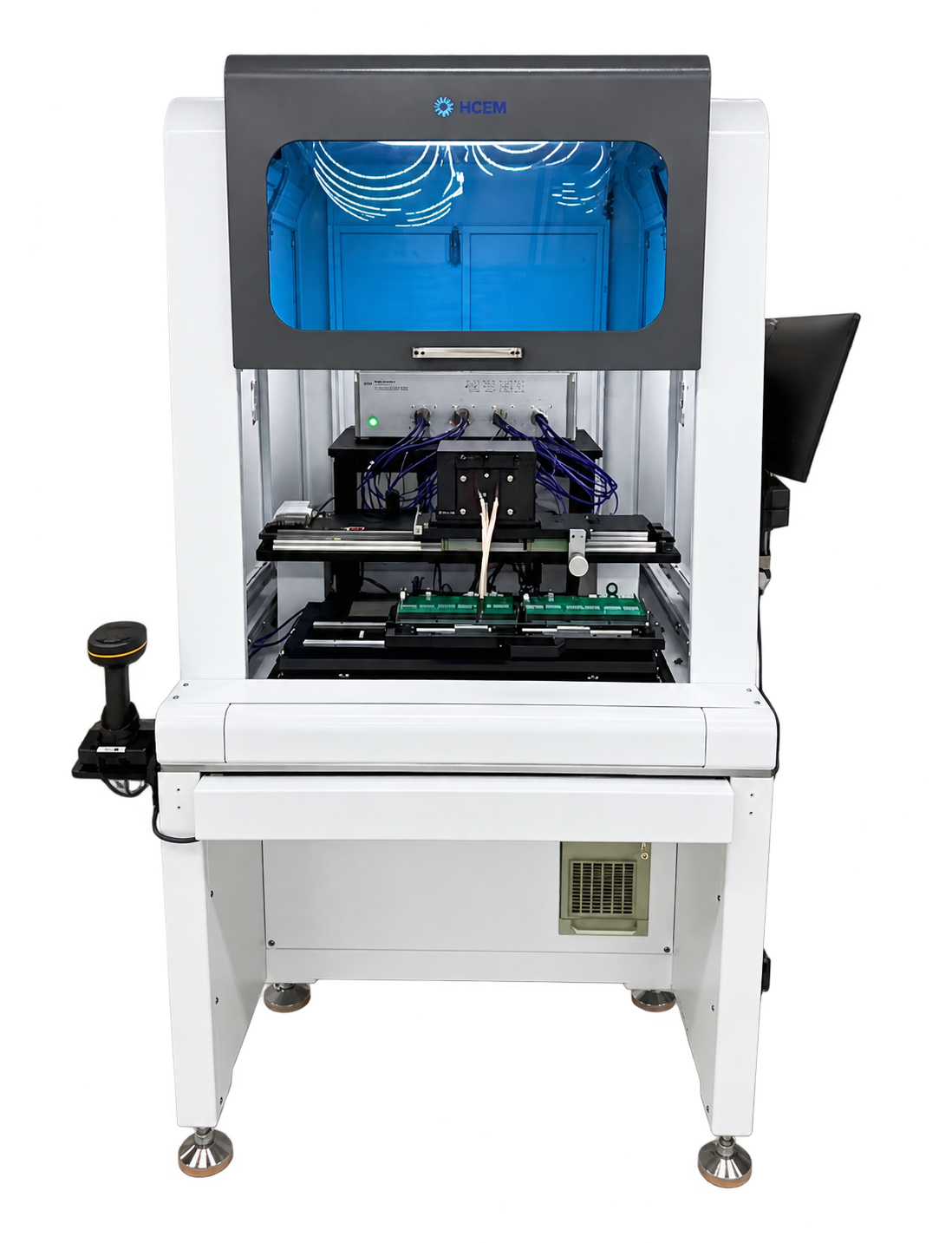
The HCEM6000 configuration presented here brings assembled-board time-domain reflectometry (TDR) measurement into a dedicated test station. Its stated applications include PCBs, connectors, and assembled-board impedance testing.
The integration challenge
A measurement instrument is one part of the setup. The probe must suit the connector, the board must be positioned for access, and the test settings must match the structure being evaluated. Changes to the probe interface can also affect the measured response.
This application therefore connects three engineering decisions: the electrical measurement configuration, the physical probe interface, and the sequence that brings them together at each test location.
The solution approach
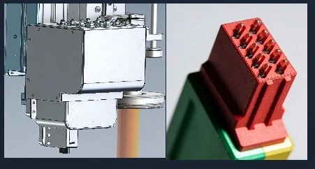
The presentation describes a tester with differential and single-ended impedance measurement, configurable impedance limit zones, and a quick-swap probe header. A matched female probe is used for the high-density connector interface, with the stated aim of reducing the probe’s contribution to the measurement.
The complete approach combines the analyzer, probe hardware, board fixture, and positioning system in one station. For a new integration project, loading, unloading, software interfaces, and the required level of automation are defined around the customer’s process.
Documented configuration
The following values are the configuration options stated on page 8 of the supplied technical presentation. They describe the presented HCEM6000 setup; the instrument, probe, and system configuration for a new project require confirmation.
| Parameter | Presented configuration |
|---|---|
| Test platform | HCEM6000 assembled-board TDR tester |
| Probe-unit port options | 1, 4, or 8 ports |
| Impedance design options | 85 or 100 ohms |
| Stated rise time | 10.4 ps |
| Bandwidth options | 50 or 67 GHz |
| Measurement modes | Differential and single-ended impedance |
| Limit evaluation | Multi-zone impedance limit settings |
| Probe interface | Matched female probe for high-density connectors |
| Changeover feature | Quick-swap probe header |
| Applications | PCBs, connectors, and assembled-board impedance testing |
What the examples demonstrate
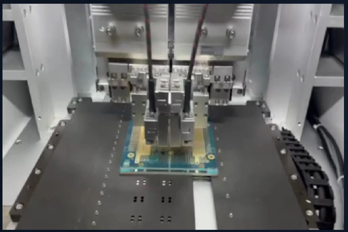
The wider presentation shows TDR traces used to examine changes along a signal path and a separate advanced-packaging failure-analysis example. In that example, traces are labeled to distinguish a reference sample, impedance deviation, and a short. An automated probing demonstration shows how mechanical access can be brought into that measurement workflow.
The examples illustrate measurement and probing methods for configuration review. A new system is evaluated against the agreed board, setup, and acceptance criteria.
Applying the approach to your board
For a Truesig integration project, we start with your board or connector drawings, target impedance, measurement range, preferred instrument, and required test sequence. We then review probe access, fixturing, positioning, and loading as one scope.
Acceptance is defined using the agreed sample boards, calibration procedure, measurement settings, limit zones, and workflow demonstration. That connects the proposed configuration to a clear evaluation plan.
Explore automated PCB test integration or discuss your application.